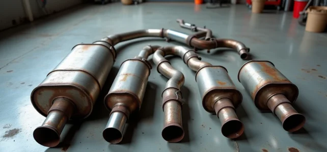
The exhaust system of a car consists of several elements assembled in series, from the manifold to the rear outlet. Identifying each part on a real vehicle, without a clear visual reference, remains a common difficulty for motorists who want to order the correct part or understand a workshop quote. An exploded view diagram allows for quick location of each component, but one must also know how to read the clues that the exhaust line itself provides.
Sensors and Mountings: The Overlooked Markers of the Exhaust Line
Most content dedicated to the exhaust system focuses on the manifold, the catalytic converter, and the muffler. These three major parts capture attention because they represent the bulk of the replacement cost. However, they are not sufficient to precisely locate a problem.
The oxygen sensors (lambda probes) are a first concrete marker. On most current vehicles, one probe is located upstream of the catalytic converter and another downstream. Identifying these two sensors on the line allows for a definite delimitation of the catalytic converter’s position, even when the part is partially obscured by a heat shield.
Consulting the car exhaust line diagram in exploded view helps visualize the exact location of these probes in relation to the rest of the line.
The mounting elements (clamps, rubber supports, bushings) are not always shown on simplified diagrams. They play a direct role in diagnosis: a worn bushing causes vibrations or a metallic rattling easily confused with a cracked pipe. Before suspecting a major part, checking the condition of these mountings can prevent unnecessary replacements.

Back Pressure and Sizing: What the Diagram Doesn’t Always Show
An exploded view diagram represents the geometry of the parts, not their aerodynamic behavior. The internal sizing of each section influences the back pressure exerted on the engine, a parameter that directly affects performance and consumption.
A partially obstructed line (clogged catalytic converter, deformed muffler) retains burnt gases and increases this back pressure. The engine loses efficiency, consumption rises, and in some cases, the ECU triggers a limp mode. Conversely, a line that is too free (removal of a filtering element, for example) alters engine behavior and makes the vehicle non-compliant with technical inspections.
The key point to remember: two visually identical parts can have different internal sections. When replacing, the manufacturer’s reference or the homologated equivalent ensures that the internal diameter matches the original calibration. Relying solely on the external shape exposes one to mismatching.
DPF and GPF on the Exhaust Diagram: Distinguishing Diesel and Gasoline
The architecture of the line varies according to the type of engine. On a diesel engine, the particulate filter (DPF) is usually located between the oxidation catalytic converter and the muffler. On some recent gasoline models, a gasoline particulate filter (GPF) occupies a similar position, which changes the total number of visible parts on the diagram.
This distinction has practical consequences when identifying:
- On a diesel, the DPF is often recognizable by its larger volume compared to the catalytic converter, and by the presence of differential pressure sensors at its ends
- On a gasoline vehicle equipped with a GPF, the filter may be integrated into the catalytic converter in a single housing, making visual separation difficult without an exploded diagram
- Older gasoline vehicles do not have either DPF or GPF, simplifying the reading of the line to three main elements (manifold, catalytic converter, muffler)
The presence or absence of a particulate filter changes the number of parts to identify. Checking the exact engine type of the vehicle before consulting a generic diagram prevents confusion between two architectures.
OBD-II Fault Codes Related to the Exhaust Line
When a check engine light comes on, reading the OBD-II codes directs the diagnosis to a specific area of the line. Codes P0420 and P0430 indicate insufficient catalytic converter efficiency. Cross-referenced with the diagram, they allow for pinpointing the affected part without dismantling the entire system.
Other codes point to the lambda probes themselves or to the DPF circuit. The exploded diagram combined with the fault codes forms a more reliable diagnostic tool than a visual inspection alone, especially on vehicles where components are hard to access.
Field Diagnosis: What a Visual Inspection Really Reveals
Visual inspection remains the first reflex, but it has its limits. Here are the actionable clues without specific equipment:
- Black soot traces around a joint or weld indicate an exhaust gas leak at that precise location
- A bluish or golden discoloration on a stainless steel tube indicates local overheating, often related to an upstream issue (too rich a mixture, clogged catalytic converter)
- Excessive play at a clamp or rubber support can be detected by gently shaking the pipe (cold engine and vehicle on jack stands)
- Pitting corrosion on galvanized steel tubes concentrates at low points where condensation stagnates, particularly near the rear muffler
These observations do not replace a pressure test or an OBD-II reading, but they help narrow down the faulty area before ordering a part. On lines made up of several bolted sections, identifying the exact section prevents replacing the entire line.
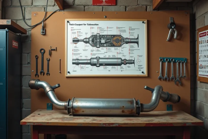
The exploded view diagram takes on its full value when cross-referenced with these physical clues. A localized soot trace between the downstream lambda probe and the muffler, for example, points unambiguously to the intermediate section. The approach remains the same regardless of the vehicle: observe, locate on the diagram, then verify the exact reference of the part in question before any order.